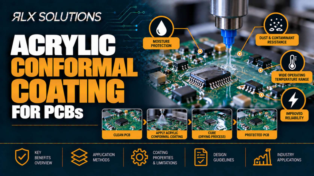
Acrylic conformal coating is a thin protective polymer layer applied to a printed circuit board after assembly to reduce exposure to moisture, dust and environmental contamination. RLX Solutions, a contract electronics manufacturer in Concord, Ontario, applies conformal coating as a post-assembly process where the board design, masking plan and inspection requirements support it.
Acrylic coating protects the board without permanently burying it
A conformal coating follows the contours of an assembled circuit board rather than filling the enclosure around it. Acrylic is one coating chemistry used for this purpose. Its practical attraction is the combination of environmental protection and comparatively straightforward rework.
The coating forms a dielectric barrier over exposed conductors, solder joints and component surfaces. That barrier reduces direct contact between contaminants and electrically active surfaces. It can also reduce the opportunity for condensation or conductive debris to create leakage paths across the board.
That does not make the assembly waterproof.
Coverage is rarely equivalent to sealing an entire product. Connectors, test points, switches, heat-transfer surfaces and other areas may need to remain uncoated. Component bodies and geometries also create shadowed areas where coating behaviour differs from an open, flat surface.
For the engineer, the useful distinction is simple: acrylic conformal coating is environmental protection applied to the assembly, while potting or encapsulation surrounds components with a much larger mass of protective material. Choosing between them changes rework access, weight, thermal behaviour and manufacturing sequence.
Three coating terms that affect the drawing
A conformal coating is a protective material that follows the geometry of the assembled PCB rather than forming a solid enclosure around it.
A keep-out is an area intentionally excluded from coating because coating could interfere with its electrical, mechanical, optical or thermal function.
Selective coating applies material to defined regions rather than treating the entire available board surface. Full-board coating covers the broader assembly while still respecting specified keep-outs.
Those distinctions belong in the manufacturing documentation. Leaving them implicit forces production to interpret design intent after components have already been installed.
Specify what must stay uncoated before defining coverage
The coating drawing should begin with exclusions, not with a vague instruction to “coat board.”
A connector illustrates why. Coating on the PCB around a connector may be useful, while coating on its mating contacts may prevent reliable electrical connection. A programming header might need to remain accessible through production test but could have a different requirement after programming. A mechanical grounding point can fail its intended function if an insulating film is introduced between conductive surfaces.
Common areas that deserve an explicit coating decision include:
- Connector mating interfaces and contacts
- Test pads and production probe locations
- Programming or debugging interfaces
- Switches and adjustable components
- Mechanical grounding or chassis-contact points
- Optical devices and sensor windows
- Thermal interfaces and surfaces intended to contact heat-transfer hardware
- User-serviceable electrical contacts
Masking converts those design decisions into a manufacturable boundary. The more irregular the boundary, the more the engineer should consider whether the protection gained is worth the masking, application and inspection work it creates.
Worked example: a 6-layer controller with production test access
Consider a hypothetical 6-layer, 1.6 mm control board measuring 120 × 80 mm. It has two board-edge connectors, eight test pads, a programming header and a power device that transfers heat into a mechanical thermal interface.
A blanket note stating “apply acrylic conformal coating” does not resolve four different requirements. The connector contacts must remain functional, the eight test pads must remain probe-accessible, the programming header needs a defined coating state, and the thermal contact surface cannot simply be treated like ordinary laminate.
A better manufacturing package identifies each exclusion on the assembly drawing and defines the intended coated region around it.
The cost consequence comes from geometry, not simply board area. A 120 × 80 mm board with one rectangular keep-out can be easier to process than a smaller board with 20 isolated exclusions around fine-pitch devices, connectors and test features. Each additional boundary creates another opportunity for masking error or incomplete coverage.
Cleanliness before coating determines what gets trapped underneath
Conformal coating does not clean a PCB. It covers the surface condition that already exists.
That makes the process sequence important. Soldering, inspection, cleaning where required, drying, masking and coating need to be considered as one chain. Applying polymer over unwanted residue can trap that residue against the assembly instead of removing the underlying contamination mechanism.
Moisture deserves the same attention. If an assembly has retained moisture or is not adequately dry for the selected process, applying a barrier over it does not reverse that condition.
This is one reason conformal coating should be treated as an assembly process rather than a cosmetic finishing operation. The coating result depends on what happened to the board before the coating material reached it.
The engineer should therefore communicate any cleanliness requirements that are specific to the product, along with coating coverage and keep-outs. If the product has an environmental requirement, that requirement should drive the coating specification rather than assuming that the word “acrylic” defines the necessary protection.
Selective and full-board coating solve different manufacturing problems
Selective coating is useful when the protected area can be defined without covering features that need continued access. Broader coating makes sense when most of the assembly requires protection and the exclusions are limited and well controlled.
Neither method eliminates masking automatically.
Consider a board with a connector along each edge, a central BGA, several exposed test pads and a high-current terminal. The central electronics may benefit from coating while several perimeter features cannot tolerate material in their functional interfaces. A selective path can reduce unnecessary coating, but the programmed application path and physical access around tall components still matter.
Component height matters because liquid coating must reach the intended surface. Tall parts can create shadowing. Closely spaced components can create narrow channels. Capillary behaviour can move liquid toward locations that were not intended to receive it.
The important manufacturing question is therefore not simply “selective or full board?” It is whether the specified coverage can actually be produced and inspected around the assembly geometry.
Board A and Board B show why coating cost is not based on layer count
Two printed circuit boards can have the same fabrication stackup and very different conformal-coating effort.
| Decision factor | Board A | Board B |
|---|---|---|
| PCB construction | 8 layers, 1.6 mm | 8 layers, 1.6 mm |
| Board size | 100 × 80 mm | 100 × 80 mm |
| Fine-pitch device | One 0.5 mm pitch BGA | One 0.5 mm pitch BGA |
| Test access | 4 exposed test pads | 18 exposed test pads |
| Connectors | 1 board-edge connector | 4 connectors on 3 edges |
| Coating boundary | Broad coated region with few exclusions | Multiple isolated coated regions |
| Masking effort | Relatively simple | More individual exclusions |
| Inspection challenge | Large continuous areas | More boundaries and shadowed areas |
| Main cost driver | Coating application | Masking, application control and inspection |
Both hypothetical boards are 8-layer designs of identical thickness and size. Their bare-board fabrication can be similar, yet Board B creates more post-assembly work because the coating has to stop and start around more functional areas.
That difference is easy to miss when coating is added to a bill of materials or assembly note late in the design cycle. The material itself may occupy only a thin film, but every keep-out creates a manufacturing decision that must be executed repeatedly.
The practical lesson is to review coating geometry while the assembly layout can still change. Moving a test pad or consolidating programming access may be much cheaper at layout stage than managing an awkward masking boundary on every production unit.
Fine-pitch packages make inspection more important, not less
Conformal coating does not replace solder-joint inspection. The soldering process has to be evaluated before the protective layer makes some surfaces harder to access.
This is particularly relevant around bottom-terminated and area-array packages. A ball grid array (BGA), land grid array (LGA) or quad-flat no-lead (QFN) package contains solder interfaces that cannot be judged solely from the top of the assembled board.
A sensible production sequence therefore resolves solder quality first, then moves into coating.
For example, take a hypothetical 10-layer, 1.6 mm board with a 0.4 mm pitch BGA, two QFNs and selective acrylic coating over the control section. The coating specification cannot compensate for an uncertain BGA joint. Inspection of hidden solder features belongs upstream of coating so the assembly is not treated as complete merely because its exterior has received environmental protection.
The same principle applies to first-article approval. Coating coverage, keep-outs and workmanship should be established on the first build before the production lot repeats the process.
Acrylic coating still has failure modes
Acrylic is useful because it provides a protective dielectric film without turning the circuit board into a permanently encapsulated block. Its limitations still have to be matched against the actual operating environment.
Incomplete coverage leaves exposed areas in locations the design expected to be protected. Component geometry, shadowing and application access can contribute.
Coating in a keep-out can interfere with connectors, contacts, probes, grounding points or other functional surfaces. This is usually a drawing, masking or process-control problem rather than a chemistry problem.
Contamination under the coating means the protective film has been applied over an unwanted surface condition. Coating cannot correct what should have been removed beforehand.
Excess material around geometry can occur where liquid accumulates or flows into a narrow region. The physical behaviour of the coating around components matters as much as the nominal coated area.
Damage during later handling or rework can break the protective film. If a component is replaced after coating, the repaired region needs a defined restoration process rather than assuming the original environmental protection remains intact.
These mechanisms are why visual appearance alone is a weak definition of acceptance. The drawing needs to establish what is protected, what is excluded and what the completed assembly is expected to withstand.
Acrylic coating and potting should not be treated as substitutes
| Decision factor | Acrylic conformal coating | Potting or encapsulation |
|---|---|---|
| Protective form | Thin film following board geometry | Larger material volume surrounding components |
| Access after application | Components remain comparatively accessible | Physical access is substantially reduced |
| Rework | More compatible with planned rework | Can make component-level rework difficult |
| Weight and volume | Lower material addition | Greater material addition |
| Keep-out planning | Important | Important, but enclosure and fill geometry also dominate |
| Typical design question | Which surfaces need a barrier? | Which parts of the assembly need to be physically encapsulated? |
The choice should follow the failure mechanism. If the requirement is a thin environmental barrier while preserving service access, conformal coating can fit that architecture. If the assembly needs physical encapsulation, treating acrylic coating as equivalent protection would confuse two fundamentally different constructions.
This distinction also affects procurement. A drawing that simply requests “environmental protection” does not tell the manufacturer which physical result the product requires.
Rework has to restore the coating system, not just the solder joint
One advantage of acrylic systems is that they can support component-level repair more readily than a heavily encapsulated assembly. But repair creates a second manufacturing process.
Suppose a hypothetical 4-layer, 1.2 mm board has a failed 0.5 mm pitch QFN inside an acrylic-coated region. Accessing the device means disturbing the protective film around the component. Replacing the QFN and producing an acceptable solder joint solves the electrical repair, but it does not automatically restore the environmental barrier.
The repaired area needs to return to the intended coating state without contaminating neighbouring keep-outs.
This is why traceability matters on coated assemblies. If a unit is repaired, the production record should distinguish the component repair from the subsequent restoration and inspection of the protected region.
Give the manufacturer coating intent, not a one-line coating note
A useful coating package tells production what the finished board must look like and which functions must remain accessible.
- Coating chemistry. State acrylic when acrylic is required rather than leaving chemistry to interpretation.
- Coverage. Identify the regions that require coating.
- Keep-outs. Mark connectors, test points, grounding areas, thermal surfaces and other excluded features.
- Assembly state. Define whether programming, testing or other operations occur before or after coating.
- Acceptance requirements. State the product-specific inspection or environmental criteria that govern the finished assembly.
- Rework expectations. Where field or production repair is expected, define how a disturbed coating region is restored.
The manufacturer also needs the ordinary assembly package around that coating instruction. A bill of materials (BOM), pick-and-place or centroid data and an assembly drawing establish what is being built and where the components belong. Coating information then becomes part of that controlled assembly definition rather than an isolated purchasing note.
Treat coating as part of the assembly flow
The strongest coating plan is established before production reaches the coating operation.
Solder paste inspection (SPI), automated optical inspection (AOI), X-ray inspection where hidden joints require it, electrical testing and first-article approval all address different risks. Conformal coating sits downstream of those assembly controls. Moving it earlier cannot compensate for an unresolved soldering or test problem.
This sequencing matters commercially as well. Discovering after assembly that 12 test points were supposed to remain exposed can create masking, rework or test-access problems that did not exist in the original layout.
Design for manufacturability and design for assembly (DFM/DFA) review is therefore useful before the coating pattern becomes a production constraint. The engineer should provide the actual coating drawing and assembly data so the review can evaluate physical boundaries rather than infer them from a general note.
Prepare acrylic-coated PCB assemblies for production
If you are specifying acrylic conformal coating on a board heading into production, RLX reviews the assembly as part of every quote. Send the Gerber data, BOM, pick-and-place data, assembly drawing and coating requirements so the build, inspection, test and coating sequence can be reviewed together before production release.
Frequently Asked Questions
Is acrylic conformal coating waterproof?
Acrylic conformal coating should not be treated as a blanket claim that a PCB is waterproof. It creates a protective film over specified circuit-board surfaces, but connectors, keep-outs, component geometry, coating coverage and the enclosure still affect environmental exposure. If a product has a defined water-ingress requirement, specify that product requirement separately from the coating chemistry.
Can connectors be conformal coated?
The surrounding PCB may be coated, but functional connector contacts generally require an explicit coating decision. An insulating polymer on a mating surface can interfere with electrical connection. The assembly drawing should identify connector keep-outs rather than relying on the coating operator to determine which portions of the connector need protection.
Can a conformal-coated PCB be reworked?
Yes, provided the selected coating and repair process support the required component access. Replacing a component is only part of the job. Removing or disturbing coating exposes the repaired region, so the coating must subsequently be restored and inspected according to the assembly requirements.
Should conformal coating happen before or after electrical testing?
The production sequence should preserve the access needed for inspection, programming and electrical test while ensuring the final assembly receives its required coating. Test pads and programming interfaces can require keep-outs if they remain accessible after coating. Defining that sequence on the manufacturing package prevents coating from obstructing a later operation.
What files should I provide for an assembled PCB that needs conformal coating?
Provide the normal manufacturing and assembly data plus clear coating instructions. Useful production data includes Gerber RS-274X, ODB++ or IPC-2581 data as applicable, NC drill data, a BOM, pick-and-place or centroid file and assembly drawing. The coating requirement should identify chemistry, intended coverage and areas that must remain uncoated.
Is conformal coating the same as potting?
No. Conformal coating creates a thin protective layer that follows the assembled PCB, while potting or encapsulation places a much larger volume of material around components. That physical difference affects component access, repair strategy, weight, thermal behaviour and manufacturing. The environmental requirement should determine which construction belongs in the product.