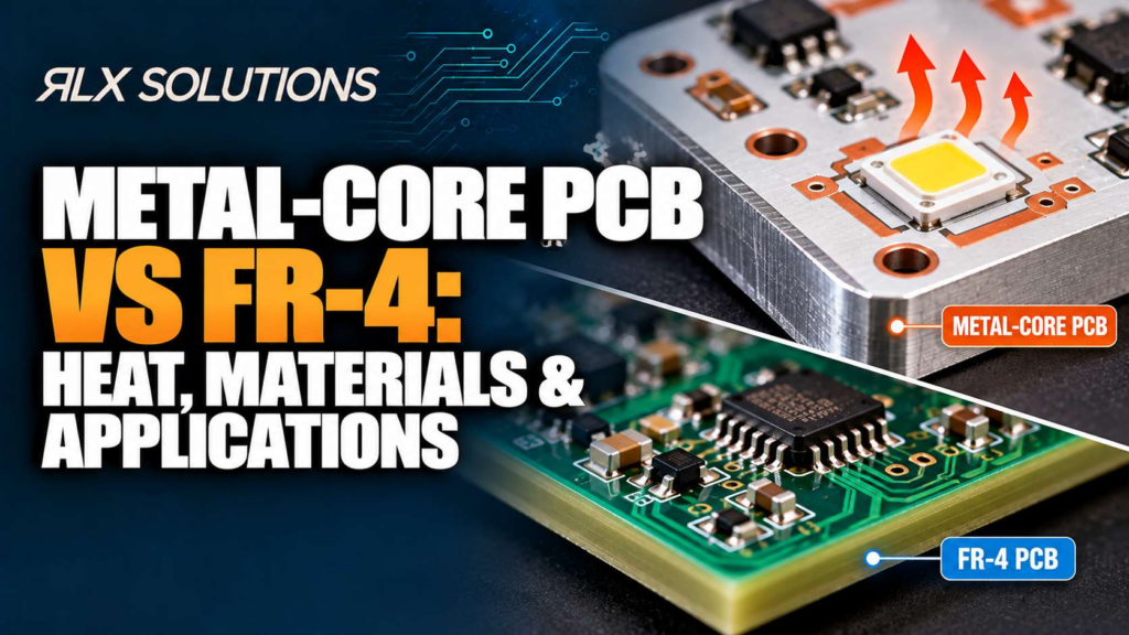
Metal-core PCB and FR-4 solve different board-level problems. Metal-core construction gives heat a short path into an aluminum or copper base, while FR-4 gives engineers greater freedom for multilayer routing and mixed-signal circuitry. RLX Solutions, a contract electronics manufacturer in Concord, Ontario, reviews substrate choice against the electrical, thermal and mechanical requirements of the board.
Metal-Core PCB vs FR-4 at a Glance
The practical difference is not simply that one material “runs cooler.” It is how each printed circuit board moves heat while maintaining electrical isolation and providing enough routing structure for the circuit. For the full picture, see our PCB Manufacturing Guide.
| Decision Factor | Metal-Core PCB | FR-4 PCB |
|---|---|---|
| Basic construction | Circuit copper, insulating dielectric and metal base | Copper bonded to glass-reinforced epoxy laminate |
| Primary thermal strategy | Move heat through the dielectric into a metal heat spreader | Spread heat through copper, planes, vias and external thermal structures |
| Metal options | Aluminum or copper core | No integral metal core |
| Routing emphasis | Well suited to circuits where the thermal path dominates the architecture | Well suited to multilayer signal, power and mixed-function routing |
| Main thermal bottleneck | Dielectric between circuit copper and metal | Laminate and the engineered path between the heat source and heat exit |
| Design advantage | Direct thermal path beneath heat-producing components | Stackup and routing flexibility |
| Common design concern | Thermal performance can be lost at the dielectric or chassis interface | Local hot spots can remain if copper and vias do not create an adequate heat path |
| Application direction | Concentrated heat sources with a defined path into a chassis or heat sink | Complex electronics where heat can be managed without making the substrate the primary heat spreader |
A metal-core printed circuit board therefore should not be selected merely because a component dissipates significant power. The first question is where that heat must travel.
If heat needs to pass almost directly from a device pad toward a metal chassis, metal-core construction can shorten that path. If the circuit needs several routing layers, controlled impedance structures, dense component fanout or numerous internal power and ground connections, FR-4 may give the layout engineer much more useful design freedom.
The Heat Path Decides the Substrate
A metal-core PCB works by placing a thermally conductive but electrically insulating dielectric between the circuit copper and a metal base. Heat generated at a component moves from the package into its pad, through the copper and dielectric, then into the metal.
The metal can then spread that heat across a larger area. It does not make heat disappear. The metal base still needs a path to the rest of the thermal system, such as a chassis, heat sink or other heat-transfer interface.
That distinction matters because the dielectric is both necessary and inconvenient. Electrically, it isolates the copper circuit from the conductive metal underneath. Thermally, it sits directly across the heat-flow path.
Its properties therefore influence the temperature difference required to move a given heat load. Changing dielectric thickness, material or contact area changes the thermal resistance even when two boards both carry the label “metal-core PCB.”
FR-4 takes a different route. FR-4 is a glass-reinforced epoxy laminate used as both an electrical insulator and structural PCB material. Instead of depending on the laminate as the principal heat-transfer medium, an engineer can use copper pours, planes, thermal pads and plated vias to redirect heat.
Consider a hypothetical power device mounted on a 1.6 mm FR-4 board. A 0.30 mm thermal-via array beneath its exposed pad can connect the top copper region to a large bottom copper area. The design has created a conductive path through the board instead of asking the FR-4 itself to carry the full thermal load.
The design question becomes more useful when stated this way: Can you build an acceptable junction-to-ambient thermal path while retaining the routing advantages of FR-4? If yes, changing substrate may solve a problem you do not have.
Metal-Core Materials Change More Than Thermal Performance
Metal-core PCB is a construction category rather than one single material system. Aluminum metal-core printed circuit boards are one option, while copper-core construction provides another approach where the thermal and mechanical requirements justify it.
The insulating layer remains central to either construction. A metal substrate without electrical isolation would place conductive circuitry directly against another conductor. The dielectric makes the structure electrically usable while forming part of its thermal path.
Material selection therefore involves several interacting requirements:
- Heat flow: The dielectric and metal structure must move heat away from the source at the required rate.
- Electrical isolation: The insulating system has to remain suitable for the circuit’s voltage requirements.
- Copper requirements: Current-carrying conductors still need appropriate copper geometry regardless of the substrate underneath them.
- Mechanical integration: The metal base needs to fit the enclosure, mounting and heat-transfer strategy.
- Assembly: Surface finish and pad design still affect solderability and component attachment.
The result is an important procurement distinction. “Aluminum PCB” is not a complete material specification. Two boards with aluminum bases can behave differently because the insulating layer, copper construction and final mechanical interface are different.
For fabrication, aluminum MCPCB can use 1100, 3003, 5052 or 6061 aluminum, while copper-core construction can use C1100 copper. FR-4 choices can include standard Tg 135°C material and high-Tg 150°C, 170°C or 180°C material. Those Tg values describe glass-transition behaviour, not thermal conductivity. High-Tg FR-4 should therefore not be treated as another name for metal-core thermal construction.
FR-4 Earns Its Place Through Routing Freedom
The strongest argument for FR-4 appears when the circuit needs vertical routing freedom as much as it needs thermal control.
A multilayer FR-4 stackup lets the layout engineer distribute signal, power and reference structures across multiple copper layers. That supports dense digital circuitry, controlled-impedance routing, internal planes and via structures that connect selected layers.
The thermal design can then be integrated into that electrical architecture. Copper can spread heat laterally. Plated through-holes can connect copper regions through the stack. Via-in-pad plated over filled vias can also provide a planar component pad where dense packages make ordinary fanout difficult.
Worked Example: A Six-Layer Controller
Assume a hypothetical 1.6 mm, six-layer control board has a processor, switching regulator and several communication interfaces. The regulator is thermally significant, but the processor also requires numerous signal connections and reference planes.
Moving the entire circuit to a simple metal-backed construction just to cool the regulator changes the architecture around one component.
An FR-4 solution might instead place the regulator on Layer 1, connect its thermal pad into a via field, use internal and bottom copper for spreading, and preserve the remaining layers for signal and power routing. The engineer can then model or test the complete thermal path rather than assuming substrate replacement is necessary.
This is where thermal and electrical design stop being separate tasks. A via that carries heat consumes routing area. A copper plane used for spreading may affect return paths. Component placement determines both trace geometry and the available area for thermal spreading.
Same Layer Count Does Not Mean the Same PCB Cost
Board cost follows manufacturing operations and material requirements, not layer count alone. Two printed circuit boards can have identical layer counts while requiring very different fabrication sequences.
Board A vs Board B
Consider two hypothetical four-layer FR-4 boards, both 1.6 mm thick.
| Factor | Board A | Board B |
|---|---|---|
| Layer count | 4 | 4 |
| Main via structure | Through-hole vias | Layer 1 to Layer 2 blind vias plus buried inner-layer connections |
| Small-hole strategy | Mechanical drilling | Additional specialised via processing |
| Component density | Moderate | Dense |
| Lamination approach | Conventional multilayer build | Sequential processing required by blind-via architecture |
| Cost driver | Standard drilling and multilayer fabrication | Additional lamination, drilling, plating and process control |
Board B does not become more expensive because “four layers” suddenly cost more. Its interconnect architecture creates more manufacturing stages.
The same reasoning applies when comparing FR-4 with metal-core PCB. Substrate price alone is an incomplete comparison. You need to compare the finished thermal architecture.
An FR-4 design that requires additional vias, large copper regions, a separate heat spreader and extra mechanical interfaces has different cost drivers from a metal-core board that transfers heat directly into an existing chassis. Conversely, specifying metal-core construction for a circuit whose thermal requirements are already manageable on FR-4 can add material and fabrication constraints without solving a meaningful system problem.
Design the Metal-Core Dielectric Before the Heat Sink
A common thermal mistake is to focus on the metal plate while giving less attention to the insulating layer immediately above it.
Thermal resistance increases with the distance heat must travel through a material and decreases as the available heat-transfer area grows. The dielectric therefore affects the temperature drop between the copper circuit and metal base.
Imagine two hypothetical LED boards using the same aluminum base and the same 2 oz circuit copper. Board X uses a thinner thermal dielectric beneath the LED pads. Board Y uses a thicker dielectric to satisfy a different electrical-isolation requirement.
Even with identical aluminum beneath them, the boards do not present identical thermal paths. Board Y forces heat through more insulating material before it reaches the aluminum.
This creates a real engineering trade-off. Thermal, electrical and safety requirements must be resolved together rather than allowing one parameter to determine the stackup.
The chassis interface matters next. Poor mechanical contact, an inappropriate thermal interface or insufficient contact area can dominate the path after the PCB has already transferred heat into its metal base.
Surface Finish and Assembly Still Matter
Changing substrate does not remove the ordinary requirements of component assembly.
The copper pads still need a surface finish compatible with the component, assembly process and product requirements. Available PCB finishes can include lead-free HASL, ENIG, ENEPIG, immersion silver, immersion tin, OSP and hard gold for appropriate applications. Finish selection affects solderability and, for some component or interconnect types, downstream processing.
Thermally significant packages also make assembly inspection more important. A carefully calculated board-level thermal path can still be compromised if the solder connection beneath an exposed thermal pad does not form as intended.
For assembled boards, solder paste inspection (SPI) before reflow can evaluate paste deposition, while automated optical inspection (AOI) addresses visible post-reflow conditions. X-ray inspection is useful for packages such as ball grid arrays (BGAs), land grid arrays (LGAs) and quad flat no-lead (QFN) devices where critical joints or thermal-pad conditions are hidden beneath the package.
That is the adjacent process engineers sometimes miss in a substrate comparison: thermal performance begins with material selection but continues through solder attachment, inspection, mechanical contact and system-level heat rejection.
Match the Board Architecture to the Application
Metal-core PCB is most compelling when the board contains concentrated heat sources and the product already provides somewhere useful for the metal base to send that heat. LED modules are a familiar example because the electrical routing can be relatively simple while junction temperature strongly influences the thermal design. Learn more about PCB material and fabrication options.
Power electronics can create a similar requirement, particularly where a small number of devices dominate heat generation. The board, enclosure and heat sink then become parts of one thermal network.
FR-4 points in the other direction when routing density or multilayer electrical structure drives the board. Digital controllers, mixed-signal systems and circuits needing numerous internal connections can benefit from keeping the conventional multilayer architecture and solving local thermal problems around the heat-producing devices.
There is no useful wattage number that universally separates the two. A 5 W loss distributed across a large board presents a different thermal problem from 5 W concentrated into a small package. Ambient temperature, airflow, enclosure construction, copper area and the final heat-exit path also change the result.
Specify the Thermal Problem, Not Just “MCPCB”
A manufacturer can make a better substrate decision when the fabrication data explains what the board must accomplish.
For a bare PCB, manufacturing data can include Gerber RS-274X, ODB++, IPC-2581 data with the NC drill information. Stackup documentation, impedance targets and fabrication notes add the requirements that geometry alone may not communicate.
For an assembled printed circuit board, the bill of materials (BOM), pick-and-place data and assembly drawing add the information needed to interpret the component side of the design.
Thermal intent should also be clear in the engineering package. Identify the significant heat sources, mechanical interfaces and electrical-isolation requirements instead of expecting the substrate name to communicate the complete design.
If you are deciding between metal-core PCB and FR-4 before releasing a board for fabrication, RLX can review the stackup and manufacturability as part of the quote process. That gives the substrate decision an engineer-reviewed design for manufacturability (DFM) review before it becomes a production constraint.
Frequently Asked Questions
Is a metal-core PCB always better for heat than FR-4?
Metal-core construction provides a direct route from circuit copper through an insulating dielectric into a metal heat spreader. Whether that produces the better system depends on the complete thermal path. FR-4 can use copper areas, planes, thermal vias and external heat-transfer structures, so the comparison should be based on junction-to-ambient performance rather than substrate name alone.
Can I use FR-4 for power electronics?
Yes. Power electronics do not automatically require a metal-core substrate. The decision depends on heat concentration, routing requirements, copper geometry, thermal vias, airflow and the available path into a heat sink or enclosure. FR-4 can also accommodate multilayer structures when the circuit needs internal power, ground and signal layers alongside its thermal features.
Is high-Tg FR-4 the same as a thermally conductive PCB material?
No. Glass-transition temperature and thermal conductivity describe different material behaviours. High-Tg FR-4 is selected where its laminate temperature characteristics suit the operating and manufacturing requirements. Metal-core PCB instead introduces a metal base and thermally conductive insulating layer specifically to create a different heat-transfer structure.
What is the difference between aluminum-core and copper-core PCB?
Both use metal as part of the board’s thermal structure, but the core material changes thermal, mechanical and manufacturing considerations. The metal still has to remain electrically isolated from the circuit copper by the dielectric system. Substrate selection should therefore consider the full stackup rather than choosing between aluminum and copper by material name alone.
Do thermal vias eliminate the need for metal-core PCB?
They can make FR-4 a practical thermal architecture in designs where vias connect a hot component region to useful copper or another heat-transfer surface. They do not guarantee equivalent system performance. Via geometry, copper area, board construction and the heat exit after the vias all affect the resulting component temperature.
What files should I send for a metal-core or FR-4 PCB quote?
For bare-board fabrication, suitable manufacturing data includes Gerber RS-274X, ODB++, IPC-2581 and NC drill files, with stackup, impedance and fabrication documentation where applicable. Assembly projects also need the BOM, pick-and-place data and assembly drawing. Providing the intended stackup and relevant thermal requirements helps keep material decisions tied to the actual design.