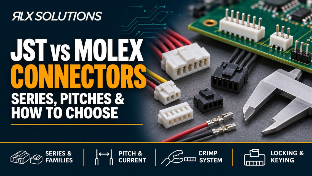
A Molex connector and a JST family are not single connector formats. Both names cover many families with different pitches, contact systems, locking methods, wire ranges and PCB interfaces, so selection starts with the exact series and part number rather than the brand name alone.
RLX Solutions, a contract electronics manufacturer based in Concord (Vaughan), Ontario, builds cable assemblies terminated with Molex and JST connector housings to customer drawings, matching the specified connector families, pinouts and conductor requirements. For an engineer or buyer, the practical task is to match the mating interface to the electrical, mechanical and manufacturing requirements before the BOM is released.
JST connector types are separate series, not interchangeable sizes
That search phrase often gets used as if JST were one plug format. It is more accurate to treat JST as a manufacturer with multiple connector systems. Pitch, housing geometry, terminal design, latch style and PCB header construction can all change from one series to another.
Four common wire-to-board families show how wide that spread can be:
- GH, 1.25 mm pitch: a compact surface-mount wire-to-board family with a secure locking structure and keying. It is used where board area is limited and a positive retention feature is useful.
- PH, 2.0 mm pitch: a small wire-to-board family offered with through-hole and surface-mount headers. It uses a friction-lock interface and supports top-entry and side-entry layouts.
- XH, 2.5 mm pitch: a larger wire-to-board family with through-hole and surface-mount header options. It also uses a friction-lock interface and is available in a broad range of circuit counts.
- VH, 3.96 mm pitch: a larger wire-to-board family with a secure lock and through-hole PCB headers. It is intended for larger conductors and higher electrical loading than the smaller GH, PH and XH examples.
A 1.25 mm housing is therefore not simply a smaller version of a 3.96 mm housing. The contact, crimp terminal, header, wire range and retention method change with the series.
That matters in procurement. A BOM line that says only “JST, 4-pin” is incomplete because it does not define the mating system. A controlled BOM should identify the housing, crimp contact, mating header or plug, circuit count, plating option where relevant and any series-specific accessory needed for the assembly.
Molex families span compact signal and higher-current series
The search term “Molex connector types” has the same naming problem. “Molex” is often used informally for many rectangular plugs, but Molex manufactures separate families that are not interchangeable even when the circuit count looks similar.
Representative families include:
- PicoBlade, 1.25 mm pitch: a compact wire-to-board and wire-to-wire system with through-hole and surface-mount header choices and a friction-lock interface.
- KK 254, 2.54 mm pitch: a modular wire-to-board and board-to-board family built around a 2.54 mm grid. Other KK families use larger pitches, so “KK” alone is still not enough for a BOM.
- Micro-Fit, 3.0 mm pitch: a compact family for wire-to-board, wire-to-wire and board-to-board connections, with positive retention options and multiple housing arrangements.
- Mini-Fit, 4.2 mm pitch: a larger family used where the design needs more conductor and contact capacity, with polarized housings and positive-locking versions.
The series name should be treated as part of the electrical and mechanical design definition. Replacing one family with another can affect the PCB footprint, mating height, wire preparation, crimp tooling, connector access and enclosure clearances.
Selection starts with the application, not pitch
A Molex family should not be selected against a JST alternative by pitch alone. Pitch is the centre-to-centre spacing between adjacent contacts, but it does not define the complete electrical or mechanical capability of the interconnect.
| Decision factor | Selected JST examples | Selected Molex examples |
|---|---|---|
| Compact pitch options | GH 1.25 mm, PH 2.0 mm | PicoBlade 1.25 mm, KK 254 at 2.54 mm |
| Larger pitch options | XH 2.5 mm, VH 3.96 mm | Micro-Fit 3.0 mm, Mini-Fit 4.2 mm |
| Retention examples | Friction lock on PH/XH; secure lock on GH/VH | Friction lock on PicoBlade; positive retention options on Micro-Fit and Mini-Fit |
| PCB mounting examples | SMT and through-hole vary by series | SMT and through-hole vary by family |
| Assembly definition | Housing, contact and mating header must match the chosen series | Housing, terminal and mating component must match the chosen family |
| Best selection basis | Circuit needs, wire, envelope, retention and exact mating pair | Circuit needs, wire, envelope, retention and exact mating pair |
The table shows why a brand-to-brand comparison is too coarse. The useful comparison is series-to-series after the circuit requirements are known.
For example, a compact 8-circuit sensor interface with small conductors and limited board edge space creates a different decision from a 4-circuit power interface with larger conductors and repeated service access. Both might be described casually as “small white connectors,” but the mechanical and production requirements point to different systems.
Pitch is a packaging constraint, not a substitute for electrical verification
Smaller pitch can reduce connector width, but it should not be used as a shortcut for current capability. Contact cross-section, conductor size, terminal material, plating, ambient temperature, number of loaded circuits and housing design all affect how a connector behaves electrically.
Consider a hypothetical 6-circuit cable carrying low-level signals on 28 AWG conductors. A compact 1.25 mm family may fit the board and cable geometry well. Now change the same cable to fewer circuits carrying higher current on 20 AWG conductors. The original pitch may no longer be the deciding factor because conductor compatibility and contact capability now dominate.
The engineering sequence should therefore be:
- Define circuit count, voltage, current per circuit and signal function.
- Define conductor gauge, insulation diameter and cable construction.
- Confirm the connector family supports that conductor and contact combination.
- Check mating retention, keying, polarization and expected service access.
- Confirm PCB footprint, orientation, insertion clearance and enclosure space.
- Verify the exact manufacturer part numbers as one mating system.
This prevents a common BOM failure: choosing a housing by appearance, then finding that the intended terminal or wire does not belong to the same connector system.
Molex connector selection depends on the full crimp system
The housing is only one part of a crimped interconnect. The contact is the element that joins the conductor to the mating pin, and its geometry is designed around a defined wire range, insulation support, mating interface and crimp process.
A substitution can fail even when the housing seems to fit. If the terminal lance does not retain correctly, the contact can back out during mating. If the conductor barrel is mismatched to the wire, the crimp can be mechanically weak or electrically inconsistent. If the insulation support is wrong, flexing can move stress into the conductor strands near the crimp.
For a manufacturing package, specify the complete connector stack:
- receptacle or plug housing part number
- crimp terminal part number
- mating PCB header or mating plug part number
- conductor gauge and insulation type
- circuit count and pin assignment
- cable length and branch dimensions
- labels, sleeving and strain-relief details where required
- electrical test requirements
The through-hole PCB assembly and soldering guide covers how leaded board components are inserted and soldered after the bare circuit board is fabricated; it does not address connector-series selection.
Locking, keying and polarization affect field behaviour
Retention features determine how much the connector depends on friction alone to stay mated. Keying and polarization control whether the mating halves can be joined in the wrong orientation or with the wrong variant.
A friction-lock family can be appropriate inside an enclosure where the cable is restrained and rarely disturbed. A positive latch can be more useful where the connection will be handled during service or where cable movement can apply repeated load to the interface. The design still has to account for the connector body, cable routing and strain relief because a latch does not remove mechanical load from the cable.
A hypothetical example shows the difference. Board A is a 4-layer controller with an 8-circuit, 28 AWG signal cable assembly inside a closed enclosure. Board B is also a 4-layer controller, but its 4-circuit, 20 AWG cable assembly is disconnected during scheduled equipment servicing. Board A may favour a compact friction-lock system. Board B gives more weight to positive retention, conductor capacity and handling.
The layer count is identical. The connector choice changes because the cable function and mechanical use changed. That difference can also change crimp tooling, operator steps, inspection points and the number of unique components in the BOM.
Do not assume equal pitch means connector compatibility
Two connectors can share the same nominal pitch and still be completely incompatible. Pitch describes contact spacing, not housing width, pin shape, contact depth, latch geometry, polarization or terminal construction.
This is especially relevant when engineers inherit older assemblies. A drawing may say “2.5 mm connector” without a manufacturer part number. That dimension narrows the search, but it does not identify the series. The mating half should be identified from the housing markings, mechanical drawing, contact geometry and board header before a replacement is approved.
The same rule applies to visually similar headers. A 2.54 mm grid is common across many product families, but a matching grid does not establish mating compatibility.
For procurement, approved alternates should therefore be validated at the full mating-pair level. A substitute should be checked against the electrical requirement, mechanical envelope, terminal system, polarization, PCB footprint and cable assembly process rather than accepted because the pitch and circuit count match.
PCB mounting method changes the assembly route
Connector selection also affects how the circuit board is assembled. Some connector families offer surface-mount headers, some use through-hole headers, and some provide both. The choice can influence stencil clearance, placement access, soldering sequence, inspection and mechanical loading around the board edge.
A surface-mount header can stay inside the normal SMT sequence if its package and process requirements fit the build. A through-hole header adds insertion and through-hole soldering after or around the SMT operations. If the connector body blocks access to nearby components, placement order and inspection access need to be considered during layout.
The separate SMT versus through-hole comparison explains those mounting technologies in detail. The connector decision here is narrower: choose the header style that fits the mechanical load, board layout and intended manufacturing sequence.
Small rectangular connectors and circular connectors solve different interface problems
JST and Molex rectangular wire-to-board families are often used inside equipment, but they are not the only connector architecture an engineer may need. External industrial interfaces can put more weight on environmental sealing, coding, shielding, repeated mating and field wiring.
The guide to M12 connector coding covers A, B, D and X coded M12 interfaces used for different industrial signal and network functions rather than small internal wire-to-board selection.
The article on MIL-DTL-38999 and circular connectors covers circular connector construction and military-style interface considerations rather than JST or Molex board-level families.
This distinction helps prevent category errors. A connector that is compact and effective inside an enclosure may not address the mechanical or environmental requirements of an external machine interface.
Worked comparison: same 4-layer board, two valid connector paths
Consider a hypothetical 4-layer control board with an 8-circuit low-voltage interface. The board needs a cable connection near one edge, and the enclosure limits connector height.
Option A uses a 1.25 mm wire-to-board family with 28 AWG conductors. The smaller pitch helps reduce connector width. The crimp contacts, housing and PCB header are selected as one family, and the cable is restrained inside the enclosure.
Option B uses a 3.0 mm wire-to-board family with larger conductors because four of the eight circuits now carry substantially more current. The connector occupies more board-edge space and can require a different header footprint, housing, terminals and crimp setup.
The PCB still has four layers. The circuit count is still eight. What changed is the conductor and electrical requirement. Option B can create more material and assembly effort because the mating system, tooling setup and cable construction differ even though the circuit board architecture did not change.
This is why connector sourcing should start from the controlled interface specification, not a photograph or a generic family name.
Freeze the connector definition before releasing the BOM
A production BOM should make the connector unambiguous. For each terminated end, include the manufacturer, exact series, housing part number, contact part number and mating component. The drawing should identify pin 1, circuit numbering, wire colours where controlled, conductor size, strip and crimp requirements, cable length and any branch points.
For cable assemblies, the connector drawing and pinout should agree with the BOM. If the drawing calls pin 1 ground but the wiring table assigns that conductor elsewhere, the assembler has two conflicting sources of truth. That conflict should be resolved before termination begins.
For cable workmanship, the manufacturing package should also state any program-specific inspection or electrical-test requirements that need to be applied to the completed assembly.
Request a Line-Item Cable Assembly Quote
Send your harness drawing, wire list and connector part numbers. RLX Solutions builds custom wire harnesses and cable assemblies to customer drawings, from low-volume prototypes to production, with 100% electrical test for continuity, opens, shorts and pin assignment. Request a quote or send your files to sales@rlxsolutions.com.
Frequently Asked Questions
Are connectors from JST and Molex interchangeable?
No. JST and Molex are manufacturers with many separate connector families. Even if two parts share the same pitch and circuit count, their housings, contacts, latches, polarization and mating dimensions can differ. Treat compatibility as a part-number and mating-interface question. Verify the exact housing, terminal and mating header or plug before approving any substitution.
How do I identify an unknown connector from JST or Molex?
Start with the manufacturer markings, circuit count, measured pitch, housing dimensions, latch style and mating-header geometry. Then compare those features with manufacturer drawings. Pitch alone is not enough because several families can use similar spacing. If the connector is already terminated, the conductor size and visible contact shape can also help narrow the series.
Which connector pitch should I choose for a PCB cable?
Choose pitch after defining circuit count, conductor size, current, voltage, board space, mating direction and retention needs. A smaller pitch can reduce board-edge width, while a larger family may accept larger conductors or different retention structures. Verify the exact series data rather than assuming that a given pitch automatically supports a particular electrical load.
What information should be on a cable assembly drawing?
Include connector and contact part numbers, pin numbering, conductor size, wire or cable type, cut length, branch dimensions, labels and any sleeving or strain-relief requirements. Add a clear wiring table that maps each conductor from one end to the other. The drawing, BOM and pinout should use the same circuit numbering so there is no conflict during termination or test.
Can I replace a discontinued connector with one that has the same pitch?
Possibly, but equal pitch is only the first filter. The replacement must also be checked for PCB footprint, mating dimensions, conductor range, terminal construction, polarization, latch behaviour, electrical requirements and enclosure clearance. If the mating half already exists in installed equipment, changing the connector family can also force a change to the opposite side of the interface.