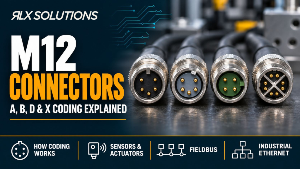
An M12 connector uses mechanical coding to keep electrically different interfaces from mating even when their threaded shells look similar. A coding is common for sensors and actuators, B for fieldbus connections such as PROFIBUS, D for 100 Mb/s Industrial Ethernet, and X for higher-speed Ethernet using four differential pairs. RLX builds M12 cable assemblies to the code, pinout and cable construction shown on the customer drawing.
RLX Solutions, a contract electronics manufacturer based in Concord (Vaughan), Ontario, terminates coded M12 connector cable assemblies from prototype to production and checks every pin assignment with 100% electrical test.
The coding letter does not define the entire interconnect. Engineers still need to confirm contact count, gender, pin assignment, cable construction, shielding, environmental requirements, and the mating device. For procurement, the safest rule is to treat coding as the first compatibility gate, not as a complete part description.
How M12 connector coding works
M12 connector coding is a mechanical polarization system built into the mating face. The shell may use the same M12 form factor, but the key and insert geometry differ by code. That physical difference is intentional: a D-coded plug should not mate with an A-coded receptacle simply because both have four contacts.
IEC 61076-2-101 covers screw-locking M12 circular connectors across several coding and contact arrangements. IEC 61076-2-109 covers X-coded M12 data connectors. The practical result for an engineer is simple: identify the code before reading the pinout, because pin number alone does not tell you what electrical function is present.
Three details cause many specification errors:
- The same contact count can exist under different codes. A 4-position A-coded interface and a 4-position D-coded interface serve different jobs and use different keying.
- The same code can appear with different contact counts. A-coded parts, for example, are available in several configurations for sensor, actuator, signal, and fieldbus use.
- A pinout drawing has a viewing direction. A male mating face and the corresponding female mating face appear mirrored. A cable drawing should state whether the view is from the mating face or the wire side.
Coding prevents one class of mechanical mistake. It does not prove that the selected cable, shield termination, conductor size, or electrical assignment matches the equipment.
A-coded M12 covers common sensor and actuator interfaces
A coding is the broad signal-oriented member of the group. It is widely used for industrial sensors, actuators, I/O, IO-Link, and selected fieldbus connections. Common versions include 3-, 4-, 5-, and 8-position arrangements, so an A-coded callout still needs a contact count and exact pin assignment.
A typical 4-position IO-Link port illustrates why the drawing matters. A common arrangement uses pin 1 for L+, pin 3 for L-, and pin 4 for the C/Q communication channel, while pin 2 can have an additional I/O or supply function depending on the port class and device. That is a protocol-specific use of an A-coded connector, not a universal statement that every 4-position A-coded cable follows the same equipment function.
Worked example: a 24 V IO-Link sensor branch
Consider a hypothetical machine with a 24 V sensor connected through a 4-position A-coded interface. The device drawing identifies pin 1 as L+, pin 3 as L-, and pin 4 as C/Q. The cable drawing must preserve those assignments end to end.
Now compare a 4-position D-coded cordset. It also has four contacts, but it is keyed for Ethernet use and its conductors are arranged around differential data pairs. Selecting it because the contact count matches fails before electrical validation. The code, protocol, and pin map all disagree with the sensor port.
For procurement, specify the manufacturer part number where possible. If an equivalent is allowed, define the code, contact count, gender, termination style, cable construction, electrical assignment, and environmental requirements instead of writing only “M12, 4-pin.”
B-coded M12 keeps fieldbus wiring distinct
B coding is associated with fieldbus systems, especially PROFIBUS. A common B-coded implementation uses five positions, with the insert keyed differently from A-coded parts so signal wiring cannot be confused at the mating interface.
This matters because fieldbus performance depends on more than continuity. The cable construction, pair arrangement, shield strategy, termination architecture, and network topology all affect the communication link. A connector that fits the enclosure and has the expected number of contacts is still wrong if it does not match the fieldbus interface defined by the equipment.
For an existing machine, the equipment datasheet should decide the code. Do not replace B coding with A coding because a sensor cable is easier to source, and do not assume a D-coded Ethernet part is a functional substitute for PROFIBUS. Mechanical coding exists specifically to keep those interface families separated.
A useful drawing note identifies both the code and the network role, for example “M12 B-coded, 5-position, PROFIBUS interface,” followed by the connector part number and pin assignment. That removes ambiguity for both purchasing and cable assembly.
D-coded M12 is the 4-position Fast Ethernet option
D coding is used for Industrial Ethernet links that operate over two twisted pairs. It is commonly specified for 100 Mb/s connections such as PROFINET, EtherNet/IP, EtherCAT, and other 100BASE-TX-based industrial networks. The familiar implementation is a 4-position interface.
The mechanism behind the four contacts is straightforward. Two conductors form one differential pair and two form the second. The connector and cable therefore have to preserve pair identity through the termination. Splitting a pair, changing the twist geometry too early, or handling the shield inconsistently can create a cable that passes a simple continuity test but performs poorly as a data link.
A D-coded cable can also bridge to RJ45 at the cabinet or switch side when the system architecture calls for it. In that case, the cable drawing should define the M12-to-RJ45 mapping rather than leaving the assembly operator to infer it from wire colours.
The EMI and EMC PCB design guidelines cover current return paths, common-mode behaviour, connector boundaries, and shielding at board level; this M12 guide stays focused on selecting and specifying the external interconnect.
X-coded M12 extends Ethernet to four differential pairs
X coding is the higher-bandwidth Ethernet option in this group. It uses eight contacts for four twisted pairs and is associated with Category 6A-class industrial Ethernet assemblies supporting links up to 10 Gb/s. The connector face separates the pair groups physically, which helps control coupling between pairs at the interface.
That architecture changes the cable assembly. A two-pair D-coded cable cannot become an X-coded cable by changing only the connector. X coding requires the complete four-pair construction, suitable shielding, correct pair mapping, and termination geometry that preserves the intended data path.
Worked example: same machine route, different network requirement
Take two hypothetical 5 m network assemblies installed along the same machine frame.
Assembly A connects a 100 Mb/s PROFINET I/O block. The device specifies a 4-position D-coded interface using two twisted pairs.
Assembly B connects a 10 Gb/s industrial vision node. The device specifies an 8-position X-coded interface using four twisted pairs and a shielded Category 6A cable construction.
Both assemblies use an M12-style circular interface at the machine end, and both may occupy the same physical route. They are not interchangeable. Assembly B has twice the data-pair count, a different mating face, and different cable-performance requirements. The network requirement determines the code before jacket material or exit angle is selected.
A, B, D and X coding compared
The comparison below is a selection aid, not a substitute for the mating device datasheet.
| Decision factor | A-coded | B-coded | D-coded | X-coded |
|---|---|---|---|---|
| Primary role | Sensors, actuators, I/O, IO-Link, selected fieldbus | Fieldbus, especially PROFIBUS | 100 Mb/s Industrial Ethernet | Higher-speed Industrial Ethernet |
| Common contact arrangements | Several, including 3, 4, 5 and 8 | Commonly 5 | 4 | 8 |
| Data conductor structure | Depends on application | Fieldbus cable construction | Two twisted pairs | Four twisted pairs |
| Example protocols | IO-Link, DeviceNet, CANopen | PROFIBUS | PROFINET, EtherNet/IP, EtherCAT | Gigabit and 10 Gigabit Ethernet |
| Main selection risk | Assuming all A-coded pinouts are the same | Substituting a general signal cable for fieldbus cable | Treating any 4-contact M12 as Ethernet-capable | Treating X as a connector-only change from D |
The table shows why the coding letter is useful but incomplete. An engineer specifying D coding has identified the interface family, but still has to define the cable category or construction, shield requirements, connector gender, pin map, jacket, flex requirement, and termination at the opposite end.
Choose by protocol first, then validate the whole cable assembly
Start with the device interface, not with a catalogue photo. A procurement description should be traceable back to the electrical and mechanical requirements of the equipment.
Use this sequence:
- Identify the protocol or circuit function. Sensor I/O, IO-Link, PROFIBUS, 100 Mb/s Ethernet, and 10 Gb/s Ethernet point to different interconnect needs.
- Read the device connector callout. Record the exact coding, contact count, and gender from the equipment drawing or datasheet.
- Confirm the pin assignment. State signal names by pin number and define the drawing view.
- Define the cable construction. Specify conductor count, pair structure, shield type where required, conductor size, and jacket material.
- Set the mechanical requirements. Include straight or right-angle exit, cable diameter constraints, flex or fixed installation, strain relief, and overmoulding requirements if used.
- Set the environmental requirements. The required ingress protection, temperature range, chemical exposure, and flex duty belong in the assembly specification. “M12” by itself does not establish the full environmental performance of the finished cable.
- Define the opposite termination. M12-to-M12, M12-to-RJ45, flying leads, or another connector needs its own part number and pin map.
- State the test requirements. Continuity and correct pin assignment are the baseline electrical checks. Network-specific or shielding verification should be specified where the program requires it.
This order reduces substitution errors. It also prevents a buyer from approving an apparent equivalent based only on shell size, contact count, or connector appearance.
The JST vs Molex connector guide covers board-to-wire connector series, pitches, and selection criteria, while this article addresses coded circular interfaces for industrial cabling. The MIL-DTL-38999 and circular connectors guide covers another circular-connector family and its application logic rather than M12 code selection.
Cable construction and termination still control performance
The connector code solves mating compatibility. The cable build determines whether the intended electrical interface survives the path between devices.
For D- and X-coded Ethernet assemblies, maintain the designed twisted-pair structure close to the termination. Excessive untwist changes the local relationship between conductors. Shield termination also needs a defined path when the system requires it, because a shield that ends unpredictably at the connector can change high-frequency behaviour.
For moving equipment, the jacket and conductor construction need to match the flex duty. A cable used on a fixed sensor bracket sees a different mechanical cycle from one routed through a cable carrier or robot axis. Strain relief matters because conductor motion near the termination can load crimps, solder joints, or contact interfaces even when the connector shell itself remains secure.
For sealed assemblies, the complete mated system matters. Connector body design, cable jacket, overmoulding or gland construction, assembly workmanship, and correct coupling all contribute to the environmental result. Do not copy an ingress rating from one component and assume the finished assembly inherits it automatically.
The industrial PCB manufacturing guide covers design, fabrication, assembly, sourcing, inspection, and production planning for circuit boards; it complements this cable-focused discussion without repeating the connector-coding decision.
Build the drawing so purchasing cannot misread it
A clear cable drawing should let engineering, procurement, assembly, and inspection reach the same interpretation without verbal context. For an M12 assembly, include at least:
- Connector manufacturer and part number, or an approved-equivalent rule
- Coding letter and contact count
- Male or female interface
- Straight or angled body
- Pin number, signal name, and wire identification at both ends
- Cable construction, including twisted pairs and shielding where applicable
- Jacket material and outside-diameter requirement
- Finished assembly length and tolerance
- Shield termination method where required
- Overmould, gland, boot, or strain-relief requirements
- Labels, markers, or serialization if the program needs them
- Electrical and program-specific test requirements
- Drawing revision and acceptance criteria
Avoid a BOM line that says only “M12 cable.” That description leaves open the code, contact count, gender, cable architecture, pin map, and opposite-end termination. A substitution made under that level of ambiguity can be mechanically wrong, electrically wrong, or both.
If a cable interfaces directly with a printed circuit board through a panel receptacle or board connector, also verify the receptacle orientation and board-side pin numbering. A front-view connector sketch copied into a PCB drawing without view notation is a common path to mirrored assignments.
Request a Line-Item Cable Assembly Quote
Send your harness drawing, wire list and connector part numbers. RLX Solutions builds custom wire harnesses and cable assemblies to customer drawings, from low-volume prototypes to production, with 100% electrical test for continuity, opens, shorts and pin assignment. Request a quote or send your files to sales@rlxsolutions.com.
Frequently Asked Questions
Can A-coded and D-coded M12 connectors mate if both have four pins?
No. The coding changes the key and insert geometry, so an A-coded 4-position connector and a D-coded 4-position connector are intentionally different mating interfaces. The matching contact count does not make them interchangeable. A coding is common in sensor and actuator applications, while D coding is used for two-pair Industrial Ethernet.
What is the difference between D-coded and X-coded M12 Ethernet connectors?
D coding commonly uses four contacts and two twisted pairs for 100 Mb/s Industrial Ethernet. X coding uses eight contacts and four twisted pairs for higher-bandwidth Ethernet, including Category 6A-class 10 Gb/s applications. The mating faces are different, so X coding is not a drop-in replacement for an existing D-coded port.
Is every 4-pin M12 connector wired the same way?
No. Contact count does not define coding or electrical function. A 4-position A-coded sensor connection and a 4-position D-coded Ethernet connection can use different keying, cable construction, and pin assignments. The equipment datasheet and cable drawing should identify the coding, pin numbers, signal names, gender, and viewing direction before the assembly is built.
Which M12 coding is used for PROFIBUS?
B coding is commonly associated with PROFIBUS fieldbus connections, often in a 5-position form. The cable still has to match the network specification, including the assigned contacts, cable construction, shielding, and termination arrangement. Do not substitute an A-coded sensor cable or a D-coded Ethernet cable solely because the connector body looks similar.
What information should I include in an M12 cable assembly RFQ?
Include the connector part numbers, A/B/D/X code, contact count, gender, pin-to-pin map, cable construction, assembly length, jacket requirement, shielding and shield termination where applicable, strain relief or overmould details, environmental requirements, and test criteria. Also identify the mating device or provide its interface drawing so the cable definition can be checked against the actual port.