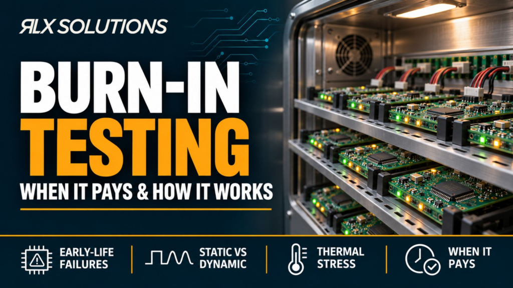
Burn in testing applies controlled electrical and thermal stress to electronics so latent defects are more likely to appear before the product enters service. It is used to expose early-life failures that may not show up during a brief functional check. It pays when the consequence of an early failure justifies added screening and the stress profile targets a credible failure mechanism.
RLX Solutions, a contract electronics manufacturer based in Concord (Vaughan), Ontario, provides PCB assembly with burn-in screening available for builds with defined inspection and test requirements. Burn-in testing is available on request.
Burn In Testing Screens for Early-Life Failures, Not Every Failure Mode
Electronic failure rate is often described with the bathtub-curve model: higher early-life failures, a lower and flatter useful-life region, and a later rise as wear-out mechanisms become dominant. Burn-in is a screening method aimed at the first part of that curve. It applies stress before release so weak devices or assemblies have a greater chance of failing under controlled conditions instead of after deployment.
The key word is screening. A burn-in screen does not prove that a product will survive its complete service life. It also does not replace design validation or reliability qualification. Its job is narrower: increase the chance of finding latent early-life defects before accepted hardware leaves manufacturing.
Those defects can involve components, assembly conditions, contamination, marginal electrical behaviour, thermal sensitivity or damage that a short inspection or functional sequence does not reveal. The stress must therefore be chosen around the suspected failure mechanism. A hotter chamber or a higher load is not automatically a better test.
A useful engineering definition is this: burn-in is controlled pre-service operation under specified stress, monitoring and pass/fail limits, with the purpose of screening early failures.
Burn-In Belongs After Basic Assembly Defects Have Already Been Screened
Burn-in should not be the first serious test a printed circuit board assembly sees. Assembly inspection and electrical checks are better at finding many defects that do not require sustained stress to expose.
A typical sequence can include:
- Solder paste inspection before reflow.
- Automated optical inspection after reflow.
- X-ray for hidden joints such as BGA, LGA and QFN connections where required.
- Manual workmanship inspection.
- In-circuit or connectivity testing.
- Customer-defined functional testing.
- Burn-in when the product-specific screening plan calls for it.
- A final functional check and record review after the screen.
The sequence matters because burn-in can tell you that a unit failed under stress, but it may not tell you why. If gross assembly defects are already screened, failure analysis starts with a narrower field.
For the upstream manufacturing flow, the PCB assembly process from solder paste through final testing explains how inspection and electrical verification build evidence at different stages. AOI inspection and its visibility limits covers what optical inspection can catch and what remains hidden. Flying-probe versus in-circuit testing addresses electrical access and fixture trade-offs before a longer stress screen is considered.
A Burn In Test Is a Controlled Stress Sequence With Defined Monitoring
A burn in test is useful only when the conditions, measurements and failure rules are explicit. “Power the boards and leave them running” is not a test specification.
A practical profile defines the following:
- Device state: powered but idle, executing firmware, switching loads, communicating, or running a representative operating sequence.
- Electrical conditions: input rails, load conditions, current limits and any programmed operating modes.
- Thermal conditions: ambient or chamber conditions, self-heating expectations and any temperature points that must be monitored.
- Stimulus: digital traffic, sensor simulation, actuator commands, memory activity or other inputs needed to exercise the intended paths.
- Measurements: rail voltage, current, temperature, communication status, output accuracy, fault flags or other product-specific parameters.
- Failure response: whether a fault stops power, records a timestamp, isolates the unit or allows controlled continuation.
- Acceptance criteria: what counts as pass, fail, recoverable event or investigation-required event.
- Pre- and post-screen checks: the functional or electrical tests used to establish condition before and after stress.
- Traceability: which serial number or unit identifier is linked to each test record.
The physics behind the screen is acceleration. Temperature, voltage, load and switching activity can increase the rate at which some weak mechanisms reveal themselves. But acceleration is useful only if the applied stress is relevant to the product and remains inside the validated screening plan. An uncontrolled stress can create damage that would not have appeared in normal service.
Static and Dynamic Burn-In Exercise Different Failure Mechanisms
Static burn-in keeps the device biased or powered in a defined state. Dynamic burn-in actively exercises circuitry through clocks, firmware, switching loads, interfaces or changing operating states. The second approach generally provides more path coverage, but it also needs more test control and monitoring.
Consider a hypothetical six-layer controller with a 24 V input, a 5 V conversion stage, a 1.2 V processor rail and several digital outputs. A static screen might keep all rails active and monitor current, temperature and fault status. A dynamic screen could also cycle output loads, run communications traffic and exercise memory while the unit is under thermal stress.
If the concern is a marginal regulator that drifts under sustained load, static bias at low activity may not reproduce the relevant condition. If the concern is a logic path or interface that fails only while switching, an idle powered board can miss it entirely.
Dynamic does not mean “better” in every case. It means the stimulus has to match the failure mechanism you are trying to expose.
Thermal Stress Must Be Treated as a Board-Level Heat-Flow Problem
The chamber setpoint is not the same thing as every component junction temperature. A power device, processor and regulator can each operate at different temperatures on the same assembly because copper area, airflow, component dissipation and thermal paths differ.
That matters because two boards in the same chamber can experience different internal stress if their loads or cooling conditions differ. A burn-in fixture that blocks airflow, changes orientation or adds cable losses can also change the thermal state.
A sound profile therefore asks where temperature is being measured and what that measurement represents. Chamber air temperature can control the environment, but it may not describe the hottest device on the PCB. Board-mounted sensing, component telemetry or other product-specific measurements may be needed when the test intent depends on actual local temperature.
For the design side of that problem, PCB thermal management through copper, vias and heat paths explains why the complete thermal route matters instead of treating heat as a single board-level number.
When Burn-In Testing Pays
Burn-in tends to make the strongest engineering case when the expected reduction in early-life escapes is worth the added fixture occupancy, power, monitoring and failure-analysis work. The decision should be tied to risk, not habit.
Conditions that can support the case include:
- An early field failure has a high service, access or system consequence.
- Failure analysis has identified a defect that becomes visible only after sustained electrical or thermal stress.
- A new component, new assembly revision or changed process introduces uncertainty that ordinary end-of-line testing does not cover.
- The product contains power stages or other circuits whose behaviour changes materially after sustained operation.
- The customer specification calls for a defined screening step and provides test conditions and acceptance limits.
- Functional behaviour depends on firmware, communication or load states that need sustained operation to expose intermittent faults.
The economic logic is simple. Burn-in adds manufacturing work. It pays when that work meaningfully lowers the probability of an early escape that would be more disruptive to investigate after release.
That is why historical failure data matters. If repeated returns point to a regulator fault that appears only after sustained load and heat, the screening profile can target that condition. If returns are dominated by wrong component placement, burn-in is an inefficient way to attack the problem because inspection and configuration control address it earlier.
Burn-In Adds Little Value When the Screen Is Not Tied to a Failure Mechanism
More test is not automatically more assurance. A poorly chosen burn-in profile can consume capacity, create ambiguous failures or stress healthy hardware without increasing useful defect coverage.
It may add little value when:
- The likely defect is already found by AOI, X-ray, ICT or a short functional sequence.
- The stress does not reproduce or accelerate the suspected failure mechanism.
- The test has no defined telemetry, so intermittent faults cannot be reconstructed.
- Pass/fail limits are vague or depend on operator interpretation.
- The screen mixes several uncontrolled stresses, making root-cause isolation difficult.
- The profile is copied from another product with different components, power density or thermal behaviour.
- A sample-based reliability study is being confused with production screening.
Burn-in should also be separated from qualification. Screening asks whether individual units contain early defects. Qualification asks whether a design or component family can meet a broader reliability requirement. The equipment may look similar, but the statistical purpose and acceptance logic are different.
Same Eight-Layer PCB, Different Burn-In Decision
Layer count alone says little about whether burn-in will create useful information. Consider two hypothetical eight-layer assemblies.
| Decision factor | Board A | Board B |
|---|---|---|
| Core function | Low-power monitoring | Power and motion control |
| Main supply | 5 V | 24 V |
| Main digital device | 0.5 mm-pitch QFP | 0.5 mm-pitch BGA |
| Operating state | Mostly steady sensing | Programmed control with switching outputs |
| Self-heating | Limited | Several active heat sources |
| End-of-line coverage | Visual inspection, ICT, functional check | Visual inspection, X-ray, ICT, firmware and functional check |
| Likely burn-in value | Low unless failure history shows time-dependent faults | Higher if sustained load exposes marginal power, thermal or programmed-state faults |
Both boards have eight copper layers. That similarity says nothing about their early-life risk or the value of sustained stress.
Board A may already have strong defect coverage if its likely failures are placement errors, open nets or immediately visible functional faults. Board B has more operating states, hidden solder joints, self-heating and power behaviour that can change under sustained load. A burn-in screen can be more informative there, but only if the profile actively exercises the relevant power and control paths.
The comparison also shows why burn-in cannot substitute for X-ray or ICT. If Board B contains a hidden BGA solder defect, X-ray can examine physical evidence and ICT may detect electrical connectivity. Burn-in may reveal an intermittent symptom, but it is a less direct diagnostic method.
First Article Approval Should Lock the Burn-In Configuration Before Repetition
A new burn-in process needs the same configuration discipline as the rest of manufacturing. The first article inspection (FAI) provides a practical release point to confirm that the built assembly, firmware, test fixture and acceptance requirements all refer to the same revision.
The RLX guide to verifying the first production-representative assembly covers that production-release gate, including revision control, component identity, inspection evidence and customer sign-off before the remaining lot proceeds.
For burn-in, the first article should confirm the test setup as well as the physical board. If firmware version A drives a load continuously while version B duty-cycles it, the electrical and thermal stress can change even when the PCB is identical. The test record must therefore identify the configuration that actually ran.
A hypothetical example makes the risk clear. Suppose a six-layer controller uses a 24 V input and three switched outputs. The assembly drawing is current, but the burn-in station still runs an older firmware image that leaves one output inactive. The board can pass a perfectly repeatable screen while one intended stress path is never exercised. Repeatability does not fix a configuration error.
Define the Manufacturing Inputs Before Requesting Burn-In
A manufacturer cannot derive a valid screening profile from Gerbers and a bill of materials alone. The product owner has to define what operating state is meaningful, what stress is permitted and what result counts as failure.
The manufacturing package should include, as applicable:
- Released PCB and assembly revision.
- BOM and pick-and-place data.
- Assembly drawing and workmanship requirement.
- Firmware or programmable-device image, with revision control.
- Power-input and load requirements for the screen.
- Required thermal conditions and measurement locations.
- Stimulus needed to exercise interfaces, outputs or communications.
- Test limits and expected outputs.
- Fault-handling rules for resets, current excursions or communication loss.
- Unit identification and record requirements.
- The pre-screen and post-screen functional test.
- Any customer-supplied fixture, cable or external load information.
The goal is a reproducible test, not a vague instruction to “run it hot.” The assembler should be able to take the same released data and produce the same stimulus, measurements and acceptance decision for every unit in scope.
Failure Data Must Lead Back to Root Cause
A useful burn-in system records enough information to distinguish a real product failure from a test-system event. Without that, the screen can create a queue of “failed” units that cannot be diagnosed.
Useful records can include unit identity, test configuration, firmware revision, measured parameters, fault timestamp, reset history and final disposition. If a unit loses communication, the record should help determine whether the cause was the PCB, power source, cable, fixture, software or external load.
This is where layered inspection and test become valuable. AOI can show whether visible placement and solder conditions were acceptable. X-ray can provide evidence for hidden joints. ICT can isolate network faults. Functional test can show whether the board performs its intended behaviour. Burn-in adds time and stress to that evidence stack.
The screen is most useful when a failure starts an investigation rather than ending one.
Send Your Files for an Assembly Quote
Gerbers, BOM, pick-and-place. An RLX engineer reads every inquiry and replies with DFM/DFA feedback and any BOM flags before your build is quoted. RLX Solutions works under an ISO 9001:2015 certified quality system. Request a quote or send your files to sales@rlxsolutions.com.
Frequently Asked Questions
Is burn-in testing the same as functional testing?
No. Functional testing checks whether an assembly performs defined operations at the time of test. Burn-in adds sustained electrical, thermal or operating stress to increase the chance of exposing early-life faults. A product can pass a short functional test and still fail later under sustained load. Burn-in therefore complements a defined functional test rather than replacing it.
Is burn-in the same as HALT or HTOL?
No. Burn-in is generally a screening process aimed at early-life failures. Highly accelerated life testing, or HALT, is a development method used to find design margins and weak points. High-temperature operating life, or HTOL, is commonly associated with semiconductor reliability evaluation. The stress equipment can overlap, but the test objective, unit population and acceptance logic are different.
Does every PCB assembly need burn-in?
No. Burn-in makes sense when sustained stress can expose a meaningful early-life failure mode and the consequence of an escape justifies the extra manufacturing work. If likely defects are already caught by inspection, ICT or functional test, a longer stress screen may add little information. The decision should come from product risk and failure mechanisms, not a blanket rule.
Can burn-in find solder-joint defects?
It can expose some intermittent faults that become visible with heat, load or operating stress, but it is not the most direct inspection method for solder quality. AOI covers visible features, X-ray can inspect hidden BGA, LGA and QFN connections, and ICT can identify electrical connectivity faults. Burn-in is better treated as an added screen for faults that require time or stress to appear.
What should I provide when requesting burn-in with PCB assembly?
Send the released manufacturing files, BOM, pick-and-place data, assembly drawing, firmware revision, operating profile, power and load conditions, thermal requirements, pass/fail limits and any required test-fixture information. Define the pre-screen and post-screen functional checks as well. The next step is to send your files or request a quote with the screening requirements included.