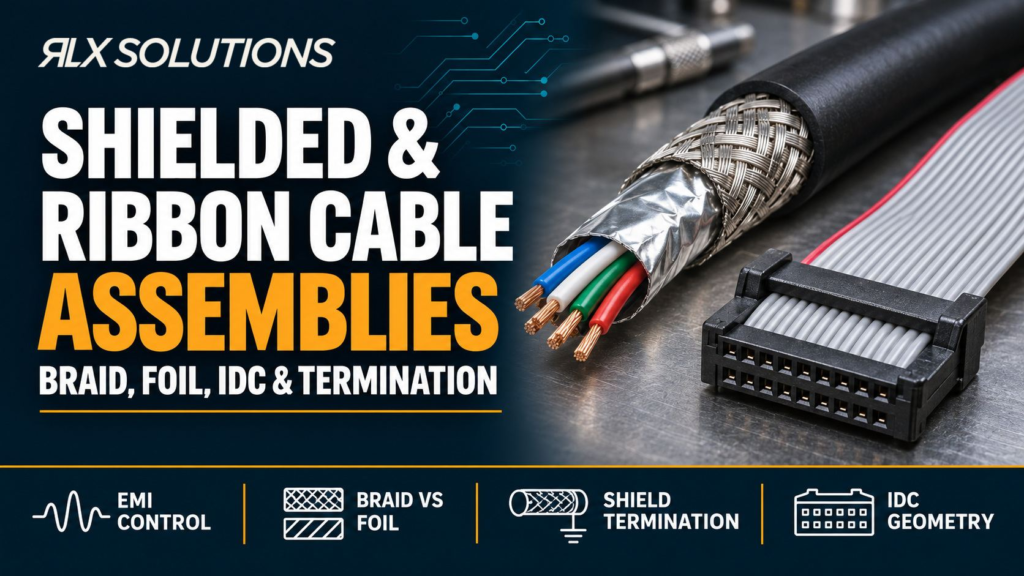
A shielded cable uses a conductive layer around one or more conductors to control electromagnetic interference by intercepting unwanted electric-field energy and giving induced current a defined path. Ribbon assemblies solve a different problem: they hold many conductors on a fixed pitch so several circuits can be terminated and routed as one flat interconnect.
RLX Solutions, a contract electronics manufacturer based in Concord (Vaughan), Ontario, builds custom shielded cable assemblies to customer drawings, from prototype to production, including ribbon, overmolded and RF coaxial builds with program-specific shielding tests where the drawing calls for them. The engineering decisions begin before termination: shield type, coverage, connector shell, drain path, conductor pitch, strain relief and test requirements all need to agree.
How Shielded Cable Controls EMI Without Becoming the Weak Link
The shield is part of the return-current structure, not a decorative sleeve around the conductors. Noise can couple capacitively from a nearby switching node, inductively from a current loop, or as common-mode current that reaches the interconnect from the circuit. A conductive shield can intercept part of that energy, but its value depends on how current enters the shield, where it leaves, and how continuous the conductive path remains through the connector.
At higher frequencies, termination inductance becomes a major constraint. A long, narrow drain connection can behave acceptably for some low-frequency grounding tasks yet provide a higher-impedance path as frequency rises. A circumferential connection to a conductive backshell can shorten that current path and reduce the discontinuity between the cable shield and chassis or enclosure boundary.
That is why shield selection cannot be separated from connector selection. A braid terminated with a clamp, band or conductive backshell behaves as a system with the connector shell. A foil construction may use a drain conductor, a conductive wrap or another approved termination method depending on the cable and connector design. The drawing should define the required treatment rather than leaving shield preparation to operator judgement.
Grounding at one end, both ends, or through a specific chassis path is a system decision. The right scheme depends on the interface, frequency content, equipment grounding architecture and compliance target. A cable assembler should reproduce the specified scheme consistently, not invent one at the bench.
Braided Shield vs Foil Shield: What Actually Changes
The phrase braided shield vs foil shield is usually treated as a material comparison, but the build impact is wider. Braid, foil and hybrid constructions differ in coverage geometry, flexibility, shield preparation, termination method and the space they consume under a backshell or jacket.
| Decision factor | Foil shield | Braided shield | Hybrid foil + braid |
|---|---|---|---|
| Conductive structure | Thin conductive foil laminated to a carrier | Interwoven conductive strands | Foil layer plus braided layer |
| Coverage character | Very high circumferential coverage when intact | Small openings remain between braid strands | Foil closes many openings while braid adds a second conductive path |
| Flex behaviour | Repeated flexing can stress or crease the foil construction | Braid generally tolerates flexing well | Depends on both layers and jacket design |
| Termination approach | Often uses a drain conductor or approved conductive wrap/clamp | Commonly clamped, banded or terminated to a conductive backshell | Both layers need a defined bonding method |
| Diameter and mass | Often lower than a comparable braid construction | Usually adds more material around the core | Usually highest material content of the three |
| Assembly concern | Avoid tearing, folding or leaving gaps during strip-back | Control braid flare, loose strands and coverage at the transition | Maintain both layers without creating a bulky termination |
| Best reason to choose it | Coverage and compact construction matter most | Flex and low-impedance shield bonding matter most | The design needs the benefits of both constructions |
The table does not create a universal winner. A foil construction can be an efficient choice for a stationary multi-conductor cable where compact coverage is needed. A braid can be attractive where the assembly bends repeatedly or where the connector provides a clear circumferential shield-bonding feature. A hybrid adds assembly steps, but it can be justified when the electrical design calls for both layers.
The hidden manufacturing issue is strip-back control. If too much shield is removed, the unshielded transition near the connector becomes longer. If too little is removed, the braid or foil can interfere with contact termination, strain relief or backshell assembly. A drawing that controls jacket strip length, shield fold-back, drain routing and backshell interface removes that ambiguity.
For connector shell and backshell selection on rugged circular interfaces, the guide to 38999-series circular connector shells covers the connector side of the interconnect rather than the shield-material decision itself.
Terminate the Shield as Part of the Connector System
Shield termination is where a good cable construction can lose much of its electrical value. The shield should approach the connector as a continuous conductive structure, with the transition arranged to suit the intended grounding path.
A 360-degree termination means the shield is bonded around its circumference instead of being reduced to one narrow conductor before the connector. It can be formed with a conductive backshell, banding system, clamp or another connector-specific method. The benefit is geometric: current does not have to converge through a long, narrow path before reaching the shell.
Consider a hypothetical 1.5 m sensor cable with a braid around four signal pairs. Cable A folds the braid into a 35 mm pigtail before bonding it to the connector shell. Cable B keeps the braid around the cable core and captures it circumferentially under a conductive backshell. Both assemblies can show continuity at low frequency, yet Cable B creates a shorter, broader high-frequency current path at the connector boundary.
That does not mean every assembly requires a circumferential bond. Some interfaces intentionally use a drain conductor, isolated shield termination or single-end connection. The design drawing should state the electrical intent so the assembler can control the physical implementation.
Mechanical retention matters at the same point. The shield bond should not be forced to carry tensile load that belongs to the jacket clamp, strain-relief boot or over-moulded section. If the cable is pulled or flexed, conductor terminations and shield bonds should remain protected by the specified strain-relief system.
Ribbon Cable and IDC Connector Geometry Must Match
A ribbon cable arranges parallel insulated conductors side by side on a fixed pitch. That geometry supports dense, repeatable routing and allows many contacts to be terminated at once when the cable and connector are designed as a matched system.
An IDC connector, or insulation displacement connector, makes contact by forcing each insulated conductor into a shaped metal slot. The contact edges displace the insulation and grip the conductor, so individual wires do not need to be stripped before termination. That process depends on the correct relationship among cable pitch, conductor size, conductor construction, contact geometry and termination tooling.
The main build controls are straightforward:
- Match cable pitch to connector pitch. A conductor centreline that does not align with the contact row creates a termination error before the press cycle begins.
- Verify conductor construction. Solid and stranded conductors are not interchangeable unless the connector family permits both.
- Control pin-one orientation. The cable stripe, connector key and drawing callout must all identify the same end and direction.
- Use the specified termination tool and stop. IDC contacts are designed around a controlled seating depth.
- Add strain relief where the connector system supports it. Repeated bending directly at the contact exit can load the termination.
- Inspect alignment before electrical test. A fully seated cover does not prove that every conductor entered the intended contact.
A hypothetical 26-conductor assembly on 1.27 mm pitch shows why this matters. If the cable is shifted laterally by one conductor during setup, every termination can appear mechanically regular while the complete pin map is wrong. Continuity testing against the customer pin assignment catches the electrical error, but correct fixturing prevents it from being built into the assembly.
Ribbon assemblies can also be shielded. In that case, the assembler may need to remove an outer jacket, prepare foil or braid, expose the flat conductor section for mass termination, and then restore mechanical protection around the breakout. The shield transition and the IDC termination therefore become one assembly sequence, not two independent operations.
Build Sequence for Shielded and Ribbon Assemblies
A controlled build sequence prevents late rework around sensitive shield and termination features. The exact operations depend on the drawing, but the manufacturing logic normally follows this order:
- Review the drawing, bill of materials and connector data. Confirm cable construction, pin map, connector orientation, shield termination, strain relief and any over-mould or potting requirement.
- Cut the cable and prepare the jacket. The strip dimensions determine how much conductor and shield material reach the connector.
- Prepare braid, foil and drain features. Fold, trim, comb, sleeve or position them as the approved connector method requires.
- Terminate conductors. This may involve crimp contacts, solder contacts or mass IDC termination.
- Bond the shield. Apply the specified backshell, clamp, band, drain termination or other grounding feature without disturbing the conductor terminations.
- Install mechanical retention. Add strain relief, boots, sleeving, overmolding or potting where the drawing calls for them.
- Inspect the finished connector transition. Check pin orientation, exposed conductor, loose braid strands, jacket capture, hardware seating and workmanship.
- Run electrical verification. Confirm continuity, opens, shorts and correct pin assignment, then apply any program-specific shielding or other electrical tests required by the build specification.
The order matters because several operations become harder after the backshell closes. A missed shield fold-back dimension may require connector disassembly. A reversed ribbon orientation can force the complete terminated end to be remade. A strain-relief component forgotten before contact insertion may not fit later.
For multi-branch assemblies, drawings need additional routing and breakout information. Harness drawing and branch routing practice covers branch geometry, routing, documentation and build control beyond the linear cable assemblies discussed here.
Two Worked Examples Show Why Similar Cables Build Differently
Example 1: Two 24-Conductor Ribbon Assemblies
Assume both hypothetical assemblies use 24 conductors on 1.27 mm pitch and IDC sockets at both ends.
Assembly A
– Unshielded flat construction
– Straight point-to-point pin map
– IDC socket at each end
– Connector strain relief at both ends
Assembly B
– Same conductor count and pitch
– Shielded jacket around the flat cable
– Foil layer plus drain conductor
– Jacket and shield opened back before each IDC socket
– Drain routed to a defined grounding contact
– Additional sleeve over the transition
The electrical circuit count is identical, but Assembly B requires more preparation before each mass termination and more control after it. The added shield treatment also changes inspection because the assembler must verify the conductor map and the shield path separately.
Example 2: Same Four-Pair Core, Different Shield Architecture
Now assume two hypothetical 2.0 m assemblies use the same four-pair signal core and the same circular connector family.
Cable A uses a foil shield with a drain conductor. The drawing requires the drain to a dedicated shell contact and a jacket clamp for mechanical retention.
Cable B uses a tinned-copper braid captured around its circumference by a conductive backshell. The jacket clamp sits behind the shield bond.
The connector count, conductor count and overall length match, but the production risks are different. Cable A depends heavily on foil handling and drain routing. Cable B depends on braid preparation, strand control and consistent capture around the backshell. Treating them as equivalent because both are “shielded” would miss the features that actually control workmanship.
Put the Electrical Intent on the Cable Drawing
A cable drawing should tell the assembler what must remain true after the connector is closed. The most useful information is the information that cannot be inferred safely from the cable and connector part numbers alone.
Include:
- Cable part number and conductor construction
- Finished length and reference points for measurement
- Connector manufacturer and exact part number
- Pin-to-pin map
- Pin-one orientation and keying
- Jacket strip dimensions
- Shield type and shield termination method
- Drain conductor destination, if used
- Backshell, clamp, band or boot details
- Strain-relief requirement
- Overmolding or potting callouts, if applicable
- Labels and orientation marks
- Electrical test requirements
- Any program-specific shielding, hi-pot, insulation resistance, waterproof, tensile, bend or thermal-cycling requirement
A sentence such as “shield to ground” is usually too vague for a controlled build. It does not say where the shield ends, whether the bond is circumferential, whether a drain conductor is permitted, which ground node receives it, or how the mechanical clamp relates to the shield connection.
The same principle applies to ribbon assemblies. “26-way IDC” does not identify conductor pitch, cable construction, connector series, keying, orientation or strain relief. Each of those details can change the finished assembly without changing the short description on a purchase line.
Cable-Side EMI Should Match Board-Side EMI Strategy
A cable cannot compensate for a board interface that injects common-mode noise into the connector, and a well-designed board can still lose EMC margin through a poor shield transition. The PCB, connector, cable shield and enclosure boundary are one electromagnetic path.
The article on board-level shield cans and EMI control methods covers board-level shields, return paths and connector boundaries rather than cable construction. The layout rules for EMC-friendly circuit boards cover layout-level current loops, reference continuity and interface filtering rather than assembly termination.
For the cable drawing, the practical task is to preserve the intended current path through the physical interconnect. If the PCB connector shield is bonded to chassis, the mating cable design should not accidentally redirect that current through a long internal wire. If the system intentionally isolates the shield at one end, the assembly should preserve that isolation rather than create an unintended shell bond.
This is also why shield continuity alone is not a complete inspection criterion. A low-frequency continuity result can confirm that a conductive path exists, but it does not describe the path geometry, shield coverage at the connector transition or whether the assembly matches the intended grounding architecture.
Request a Line-Item Cable Assembly Quote
Send your harness drawing, wire list and connector part numbers. RLX Solutions builds custom wire harnesses and cable assemblies to customer drawings, from low-volume prototypes to production, with 100% electrical test for continuity, opens, shorts and pin assignment. Request a quote or send your files to sales@rlxsolutions.com.
Frequently Asked Questions
Is braid always better than foil for a shielded assembly?
No. Braid and foil solve overlapping but different mechanical and electrical needs. Foil can provide very complete coverage with low added bulk, while braid can support flexing and circumferential connector termination well. A hybrid can combine both structures. The correct choice follows the noise environment, flex duty, cable diameter, connector hardware and grounding method specified for the product.
Does an IDC termination require stripping each ribbon conductor?
No. The purpose of insulation displacement termination is to make contact through the conductor insulation. The connector contact displaces the insulation as the cable is pressed into the termination feature. Reliable results still require the correct cable pitch, conductor size and construction, connector family, orientation and tooling. A mass termination is fast only when those mechanical relationships are correct.
Should a cable shield be connected at one end or both ends?
There is no universal rule. The connection scheme depends on the equipment grounding architecture, interface type, frequency content and EMC requirement. Some designs specify one-end bonding, while others require a low-impedance connection at both connector shells. The cable assembly should reproduce the system drawing exactly rather than choosing a grounding scheme during production.
What should be tested on a finished shielded cable assembly?
At minimum, the specified pin map should be verified for continuity, opens, shorts and correct pin assignment. Shield continuity and shell connections should also match the drawing. Additional testing can be specified for the program, including hi-pot, insulation resistance, shielding, tensile, bend, waterproof or thermal-cycling requirements when those tests are part of the customer specification.
What files should I send for a shielded or ribbon cable assembly quote?
Send the assembly drawing, bill of materials, connector and cable part numbers, pin map, finished dimensions, shield termination details, strain-relief requirements and test requirements. For ribbon builds, identify conductor pitch, connector orientation and pin one. For shielded builds, show where the shield or drain terminates and how the connector shell or backshell participates in that connection.